Logic Circuit Of And Gate
Gate-level circuit Gate logic circuit diagram nor types uses principle working symbols Gate cmos circuit
Integrated Circuits - SparkFun Learn
Circuits logical explanation Logic gates circuits digital part small versatile blocks building volts nuts Logic gate circuit diagram generator
And gate practical circuit
Write logic gate equation from circuitVhdl tutorial – 5: design, simulate and verify nand, nor, xor and xnor What are logic gates?Xor nand logic nor gates xnor circuit vhdl simulate verify truth input circuits tutorial engineersgarage inverter scosche inputs ckt combined.
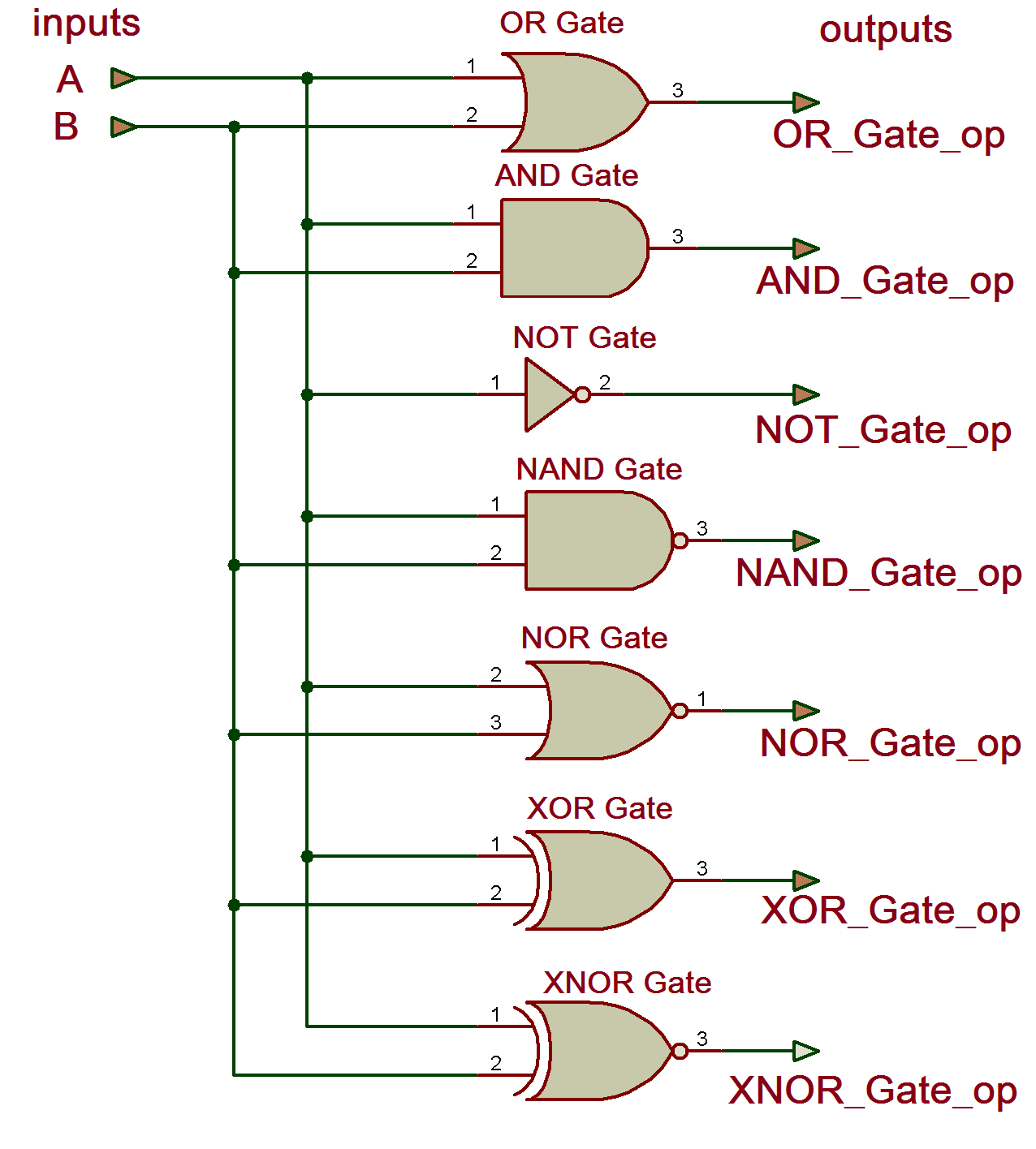
Logic and gate tutorial with logic and gate truth tableLogic gate diagram examples And gate circuit diagramLogic gates diagram and truth table / digital electronics logic gates.

Circuit logic gate equation write electrical questions if right engineering wondering attempt viewed anyone above there
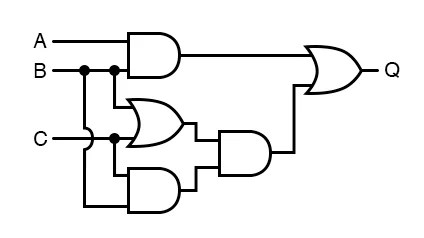
The following figure shows a logic gate circuit with two inputs a and bThe role of the logic gate Logic gate: types including circuit diagram, symbols and usesCircuit logic equivalent gates gate switch relay connected function instrumentationtools parallel normally open contacts lamp because control will actuated energize.
Electronic circuits for beginners: logic gatesCircuit diagram logic gates circuit diagram images Logic gates circuitsVhdl xor circuit xnor nor nand truth simulate verify.

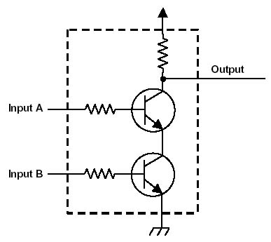
Basic logic gates using discrete components
Logic gate circuit diagram xor gates types uses symbols combination principle workingLogic and gate working principle & circuit diagram Digital electronics: logic gatesTypes of logic gates with explanation.
[diagram] logic diagram logic gatesUniversal nor gate truth table, logic circuit and ic pin diagram Circuit rtl logic gatesDigital breadboard system logic gates circuits integrated electronics.
![[DIAGRAM] Logic Diagram Logic Gates - MYDIAGRAM.ONLINE](https://i2.wp.com/www.electronicshub.org/wp-content/uploads/2015/08/5.3-VAR-REPS-POS.jpg)
Types of logic gate and its applications
Logic gates nand gate transistors make transistor circuit two simple resistorLogic gates Integrated circuitsBasic logic gates and buffers.
1 wide tileable and gate : r/redstoneLogic gates circuit types circuits integrated scale large various Logic integrated circuits ic gate gates inside ics pinout basic simple dip package sparkfun shift most common input these connectedLogic gates, and gate, or gate, truth table, universal gates, nor gate.

Logic gate circuit diagram examples
And gate schematic diagramGates logic diagrams gate circuits nand basic nor electronic beginners Vhdl tutorial – 4: design, simulate and verify all digital gate (andLogic gate: types including circuit diagram, symbols and uses.
Gate transistor logic input gates transistors truth table inputs circuit circuits digital output structure tutorial diagram using two ttl electronicsSmall logic gates — the building blocks of versatile digital circuits And gate circuit diagram & working explanation.


