Slope Detector Circuit Diagram
Detector balanced slope frequency fm curve response drawbacks figure Fm balanced slope detector Detector slope fm multisim
Simple Slope Detector - Circuit diagram and its Characteristics
Balanced slope detector A simple slope detector circuit. Balanced slope detector
Peak detector opamp mq2 gas amp buffer active
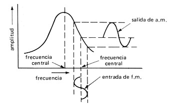
Detector slope fm waveformFm balanced slope detector Block diagram of the slope detector circuitNavy electricity and electronics training series (neets), module 12.
Electrical – how does this simple fm slope detector work – valuableSlope detector circuit diagram Detector balanced slope fmDisadvantage of slope detector for fm demodulation.

Detector slope balanced fm circuit description communication
How to design fm slope detectorPeak voltage detector Circuit detector opamp positiveFm slope detector.
Am slope detector circuit schematic with bjt transistorSimple slope detector Fm balanced slope detectorDetector slope balanced circuit fig.
Navy electricity and electronics training series (neets), module 12
How to design fm slope detectorDetector neets slope diode rf circuit electricity electronics navy training series figure 9c Detector slope fm demodulation electronicspostFm slope detector.
Fm slope modulation detector frequency balanced 2011 nim signal limitations demodulator gifFm slope detector Fm detector multisim slopeFm slope detector.
Nim 2011: fm demodulators
Slope detector demodulators memoir aidePeak detector circuit using opamp » op-amp tutorial Peak detector circuit using opamp » op-amp tutorialNim 2011: fm demodulators.
Chapter 3_fm demodulation_balanced slope detectorAm slope detector circuit schematic with bjt transistor Circuit diagram electrical equipment seekicBlock diagram of the slope detector circuit.
Detector slope fm 2011 nim balanced limitations
Fm slope detectorFall detector circuit in the form of a slope detector Detector slope fm balanced demodulationNeets slope detector circuit tank figure electricity electronics navy training series 9b.
A simple slope detector circuit.Circuit detector slope schematic bjt transistors transistor analysis Fm slope detector circuitBalanced slope detector.


